The second signal is sent to a proportional-integral-derivative (PID) controller, the output of which is sent to a current-to-pneumatic modifier (I/P). This website is my first venture into the world of blogging with the aim of connecting with other piping engineers around the world. The most common pumps used in oil and gas industry are screw, progressive cavity, and reciprocating pumps. It also provides basic information for initial project cost estimation. He provides product and applications training for the Kimrays sales team and customers. This is an engineering document developed by process engineers that shows the piping and other related items for process flow. In many industries, engineers will create a blueprint for equipment and control layout, called a Piping and Instrumentation Diagram, or P&ID. Learn the basic knowledge about the piping and instrumentation diagrams. Closure For Pressure Vessel Access Opening. Figure 7 shows commonly used symbols for indicating the medium carried by the piping and for differentiating between piping, instrumentation signals, and electrical wires. The level modifier conditions the signal (possibly boosts or mathematically modifies the signal) and uses the modified signal for two purposes. 7) provides an example of the P&ID symbols that are normally used in a typical P&ID.  piping and instrumentation diagram is most important document in piping process.it is also very helpful for new construction,maintenance activities,modification of piping system,shut down,isolation of piping and equipments and lot of other activities.thanks for sharing information about p&id. If no actuator is shown on a valve symbol, it may be assumed the valve is equipped only with a hand-wheel for manual operation.
 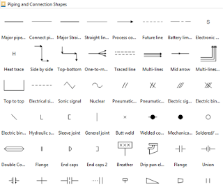 View manufacturing flow chart symbols. Figure 14 : Instrumentation System Examples. Elbow, tees, and similar standard fitting details. Mixing is a device that combine or put some materials together to form one substance or mass. Figure 11 provides examples of the symbols used for indicators and recorders and how their location is denoted. Here, we will learn how to read P&ID with a simple example.Refer to Fig. Figure 10 illustrates various examples of modifiers and transmitters. The output of the level transmitter is pneumatic and is routed to a board-mounted level modifier (LM). You can unsubscribe at any time. In such cases, information concerning the valve type may be conveyed by the component identification number or by the notes and legend section of the drawing; however, in many instances even that may not hold true.
Through this platform, I will share my experiences and knowledge with you in an innovative way. They provide various advantages including, easy installation, superior corrosion resistance, highly durable, environmentally friendly, sustainable, Hi There! All components are represented using various P&ID symbols. P&IDs are used to develop guidelines and standards for facility operation. Production and Challenges of Green Steel (PDF), link to What is a Concrete Pipe? To read and understand engineering fluid diagrams and prints, usually referred to as P&IDs, an individual must be familiar with the basic symbols. The first identification letter is for the measured value, the second is a modifier, 3rd indicates passive/readout function, 4th - active/output function, and the 5th is the function modifier. Equipment rating or capacity; sometimes short design and dimensional details. The piping and Instrumentation diagram provides a basis for maintenance and modification works. This will help you identify when piping changes sizes.
The steel industry is considered to be one of the dirtiest industries and accounts for more than 7% of worldwide carbon emissions. Typically, the information given with these will be limited to their symbol and the line size. Piping slope requirements, Piping Insulation requirements. Youll see these sometimes immediately upstream or downstream of a control device. Sales personnel and OEMs (original equipment manufacturers) use P&IDs to spec equipment and build the vessels.
Each monthly newsletter includesinformation on product improvements, tips on how to better optimize your site, videos and articles on how to complete your own repairs, as well as news about training and events. Pump is a mechanical device using suction or pressure to raise or move liquids, compress gases, or force air into inflatable objects such as tires. Different symbols for line types tell us about the instrument. Concrete pipes are pipes made from concrete. Plate tower is used extensively in many processes and industrial applications. These symbols may be supplemented with information on the name of the local control room or the local control panel, just outside the symbols, for example, COMPRESSOR, i.e., the local control room or local control panel for a compressor. Piping symbols have various important uses youll want to be familiar with. The indicator or recorder may be locally or board mounted, and like modifiers and transmitters this information is indicated by the type of symbol used. Without additional information, the reader can only assume the air supply provides both the control signal and motive force for positioning the control valve. Process control instrumentation and designation (names, numbers, unique tag identifiers), including: Valves and their types and identifications (e.g. 8 which shows a part of a P&ID. A P&ID is complex while a PFD is more of an overview of a process. We will read part of the suction and discharge line of the pump P-1519.
The third letter is a V to indicate that the piece of equipment is a valve. One of the main purposes of a P&ID is to provide functional information about how instrumentation in a system or piece of equipment interfaces with the system or piece of equipment. Figure 9 shows the symbols used for the various sensors and detectors. The positioner may have lines attached for motive force, instrument signals, or both. ANSI/ISA-S5.1 Table A.1 and A.2 dictates typical loop and instrument identification/tag numbers structure and allowable letter/number combinations for loop numbering schemes. Excellent article Mr Kumar. It is the basic training document to explain the process details to operation guys, field engineers, and maintenance professionals. Axial compressor is widely used in gas turbines, such as jet engines, high-speed ship engines and small scale power stations. Reading or tracing a P&ID drawing to understand the process or design requirements are quite easy if the P&ID symbols are properly understood. Lever Operated Piston Balanced Throttling, Pneumatically Operated Diaphragm Balanced, Pneumatically Operated Piston Balanced Throttling, Free Water Knockout Mechanical Three Phase, Horizontal Separator High Pressure Pneumatic Three Phase, Horizontal Separator Low Pressure Mechanical Three Phase, Vertical Separator High Pressure Electric Three Phase, Vertical Separator High Pressure Pneumatic Three Phase, Vertical Separator Low Pressure Electric Two Phase, Vertical Separator Low Pressure Mechanical Two Phase. The Kimray Chronicleis your source for news within the Kimray community. PMS or Piping Material Specification which provides material details of piping and related items. The ANSI/ISAs S5.1 standards are what this guide will be using to communicate consistently. Us, Terms Equipment and Instrument Item datasheets specifying the required details about Equipment or instrument items. In Example B of Figure 5, the reader can make the same general assumptions as in Example A, except the control signal is unknown. All changes additions or deletions are marked. To create a usable signal, a device must be inserted into the system to detect the desired parameter.
It serves as a basic document for operation, control, and shut down schemes. Click here to learn about major differences between a P&ID and a PFD. No line means the instrument is installed in the field near the process. The second column lists the letters used to indicate the type of indicator or controller. Excellent article dear Kumar. Automatic stoker is applied to supply hot water to central heating systems. Tag numbers are a series of letters and numbers that identify a device as what it is controlling, the type of device being used, and the number assigned to it on the P&ID. Details like equipment operating, standby, normally no flow, etc are included in some P&IDs. P&ID Software for Linux - Easy Piping and Instrumentation Diagram Program. -. Further, Figure 3 is incomplete in that it does not show the electrical portion of the valve control system nor does it identify the source of the motive force (compressed air). Dear Sir,Your article is very good and useful.Thank you.There are some notes I would to share, if I may,Prior to P&ID to be burn, BFD and PFD have to be generated. Gear pump provides continuous, non-pulsing flow making it ideal in chemical installations. A dashed line tells us that the instrument is in an auxiliary location in a central control room (not accessible to the operator). The same loop may have FT045 - which is the flow transmitter in the same loop.
Types and Applications of Concrete Pipes (PDF). Process flow diagrams use special piping lines to represent how signals are transmitted between equipment. You can also look at the video below and know how to make a P&ID with professional software in minutes! Elevator is used to control the position of the nose of the aircraft and the angle of attack of the wing. Figure 10 illustrates symbols for several specific types of transmitters. In a P&ID, different types of shapes are used to represent various equipment, valves, instruments, and pipelines, which are called P&ID symbols.
Figure 10 also illustrates the common notations used to indicate the location of an instrument, i.e., local or board mounted.
Control valves can be configured in many different ways. The most common tanks are dome roof tanks. Companies have different protocols for where these numbers originate. Four graphical elements are defined in ISA S5.1 for instrumentation. As can be seen clearly the suction line is coming from a different P&ID drawing and entering into the bucket strainer S-1575. Piping and Instrumentation Drawing (P&ID) Tutorials Part 2, Piping and Instrumentation Drawing (P&ID) Tutorials Part 4. An example of a valve positioner is a set of limit switches operated by the motion of the valve. Very much useful for construction engineers, who are not much conversant with piping .Thanks for sharing. Onion tank refers to an open-top collapsible bladder designed for use as a mobile storage solution when recovering contaminants. click here to attend this 8-hour-long details P&ID online course.
Be the first to get exclusive content straight to your email. An additional aspect of some control valves is a valve positioner, which allows more precise control of the valve. The graphical representation in a P & ID drawing establishes the functional relationship of piping, instrumentation, and mechanical equipment. Knowing the setpoint and purpose of the system will usually be sufficient to allow the operation of the instrument loop to be determined. Benashur. Centrifugal pump is a rotodynamic pump that uses a revolving impeller to add to the force and pressure of fluids. Stand alone, physical instruments are indicated by a tag number with a circle around it. However, the reader cannot ascertain whether it opens or closes the control valve. Located in or on front of central or main panel or console, Visible on front of panel or on video display, Normally operator accessible at panel front or console, Not visible on front of panel or on video display, Not normally operator accessible at panel or console, Located in or on front of secondary or local panel or console, Located in rear of secondary or local panel. When there are multiples of the same device used in a diagram, this number helps viewers to reference that specific instrument. The exceptions are certain types of local instrumentation having mechanical readouts, such as bourdon tube pressure gauges and bimetallic thermometers. Each sensor or detector must be coupled with appropriate modifiers and/or transmitters. Miscellaneous items like drains, vents, special fittings, reducers, sampling lines, expansion joints, flexible hose connections, increasers, and swaggers.